Engineering Mechanics

Engineering_Mechanics

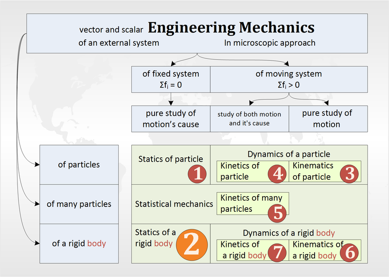
Engineering mechanics is the study of forces that act on bodies and the resultant motion that those bodies experience. Engineering mechanics subject involves the application of the principles of mechanics to solve real-time engineering problems.
Engineering Mechanics types

Types of Engineering Mechanics:

Engineering mechanics can be broadly classified into two types. They are:

  1. Statics and
  2. Dynamics

1. Statics:

Statics is the branch of mechanics that deals with the study of objects at rest. Objects at rest may or may not be under the influence of forces.

2. Dynamics:

Dynamics is the branch of mechanics that deals with the study of objects in motion and the forces causing such motion.

Dynamics Types:

Dynamics can be further classified into two types. They are:

  1. Kinematics
  2. Kinetics

2.1 Kinematics:
Kinematics is the study of motion of bodies without consideration of the cause of the motion. Kinematics deals with the space-time relationship of the motion of a body. Some examples of kinematic concepts are displacement, velocity and acceleration.

2.2 Kinetics:
Kinetics is the branch of mechanics which deals with the study of motion of bodies by considering the cause of motion.


Open Cycle Gas Turbine Plant

A simple open cycle gas turbine consists of a compressor, combustion chamber and a turbine as shown in the below figure. The compressor takes in ambient fresh air and raises its pressure. Heat is added to the air in the combustion chamber by burning the fuel and raises its temperature.

Simple open cycle gas turbine plant

Simple open cycle gas turbine plant

The heated gases coming out of the combustion chamber are then passed to the turbine where it expands doing mechanical work. Some part of the power developed by the turbine is utilized in driving the compressor and other accessories and remaining is used for power generation. Fresh air enters into the compressor and gases coming out of the turbine are exhausted into the atmosphere, the working medium need to be replaced continuously. This type of cycle is known as open cycle gas turbine plant and is mainly used in majority of gas turbine power plants as it has many inherent advantages.

Advantages:

  1. Warm-up time: Once the turbine is brought up to the rated speed by the starting motor and the fuel is ignited, the gas turbine will be accelerated from cold start to full load without warm-up time.
  2. Low weight and size: The weight in kg per kW developed is less.
  3. Fuels: Almost any hydrocarbon fuel from high-octane gasoline to heavy diesel oils can be used in the combustion chamber.
  4. Open cycle plants occupies less space compared to close cycle plants.
  5. The stipulation of a quick start and take-up of load frequently are the points in favor of open cycle plant when the plant is used as peak load plant.
  6. Component or auxiliary refinements can usually be varied in open cycle gas turbine plant to improve the thermal efficiency and can give the most economical overall cost for the plant load factors and other operating conditions envisaged.
  7. Open cycle gas turbine power plant, except those having an intercooler, does not need cooling water. Therefore, the plant is independent of cooling medium and becomes self-contained.

Disadvantages:

  1. The part load efficiency of the open cycle gas turbine plant decreases rapidly as the considerable percentage of power developed by the turbine is used for driving the compressor.
  2. The system is sensitive to the component efficiency; particularly that of compressor. The open cycle gas turbine plant is sensitive to changes in the atmospheric air temperature, pressure and humidity.
  3. The open cycle plant has high air rate compared to the closed cycle plants, therefore, it results in increased loss of heat in the exhaust gases and large diameter duct work is needed.
  4. It is essential that the dust should be prevented from entering into the compressor to decrease erosion and depositions on the blades and passages of the compressor and turbine. So damages their profile. The deposition of the carbon and ash content on the turbine blades is not at all desirable as it reduces the overall efficiency of the open cycle gas turbine plant.

Benson Boiler

With use of Benson boiler the main difficulties experienced in the La Mont boiler, the formation and attachment of bubbles on the inner surfaces of the heating tubes of boiler are resolved. The attached bubbles reduce the heat flow and steam generation as it offers higher thermal resistance compared to water film.

Benson Boiler

Benson Boiler

  1. In the year 1922 Benson argued that if the boiler pressure was raised to critical pressure of 225 atmospheres, the steam and water would have the same density and therefore the danger of bubble formation can be high.
  2. Natural circulation boilers require expansion joints but these are not required for Benson as the pipes are welded. The erection of Benson boiler is easier and quicker as all the parts are welded at site and workshop job of tube expansion is altogether avoided.
  3. Benson boiler parts transportation is easy as no drums are required and majority of the parts are carried to the site without pre-assembly.
  4. The Benson boiler can be erected in a comparatively smaller floor area. The space problem does not control the size of Benson boiler used.
  5. The furnace walls of the boiler can be more efficiently protected by using small diameter and close pitched tubes.
  6. In Benson boiler superheater is an integral part of forced circulation system, therefore no special starting arrangement for superheater is needed.
  7. Due to welded joints Benson boiler can be started very quickly.
  8. Benson boiler can be operated most economically by varying the temperature and pressure at partial loads and overloads. The desired temperature can also be maintained constant at any pressure.
  9. Sudden fall of demand creates circulation problems in this boiler due to bubble formation in the natural circulation boiler which never occurs in Benson boiler. This feature of in-sensitiveness to load fluctuations makes this boiler more suitable for grid power station as it has better adaptive capacity to meet sudden load fluctuations.
  10. The blowdown losses in this boiler are hardly 4% of natural circulation boilers of same capacity.
  11. Explosion hazards are not at all severe as it consists of only small diameter tubes and has very little storage capacity compared to drum type of boiler.

During starting of this boiler, the water is made pass through the economizer, evaporator, superheater and back to the feed line through starting valve.

During starting of this boiler, first circulating pumps are made to start and then the burners are made to start to avoid the overheating of evaporator and superheater tubes.

Liquid Chillers

Liquid chillers are machines that removes heat from a liquid via a vapor-compression refrigeration cycle or vapor-absorption refrigeration cycle. This liquid can then be circulated through a heat exchanger to cool equipment.

centrifugal water cooled chiller

centrifugal water cooled chiller.

Liquid chillers can be of two types. They are:

  1. Shell and tube type chiller and
  2. Shell and coil type chiller.

Shell and Tube type Chiller:

  • Shell and tube type of chiller consist of a steel shell, cylindrical in shape fitted with a number of parallel tubes.
  • There can be of two types in configuration in shell and tube types of chillers, when the refrigerant flows through the tubes and the liquid to be chilled (water or brine) flows in the shell, secondly the refrigerant flows in the shell and the liquid in the tubes.
  • The latter types of chillers are called flooded type chillers are called flooded type chillers and float valve is used as the expansion device.
  • When the refrigeration flows into the shell, the level of liquid refrigerant in the shell is never full, as some clear space is required for the liquid and vapor to separate.
  • In the dry expansion type chiller, the refrigerant flows through the tube and the liquid to be chilled in the shell, so that turbulence is caused in the liquid which improves the overall heat transfer coefficient.
  • Thermostatic expansion valve is used through which the liquid refrigerant is fed into the tubes.
  • Shell and tube chillers are widely used in almost all refrigeration systems as they have very high efficiency, require negligence maintenance and are adaptable to any system.

Shell and Coil type Chiller:

  •  Shell and coil type chillers consists of a shell in which tube coils are fitted. the coils are spiral shaped. Normally dry expansion type shell and coil chillers are used. The refrigerant flows through the coils and the liquid to be chilled flows through the shell.
  • The expansion device used is thermostatic expansion valve. It is used for chilling of water for drinking purposes. In the evaporator the liquid is not recalculated and is chilled instantaneously as it passes through coils.

Classification of Welding and Allied Processes

There are different joining processes welding, brazing and soldering methods are being used in industries to join, fix metals or alloys. There are different ways of classifying the welding and allied processes.

Classification can be done on the basis of source heat, fuel, type of interaction (fusion welding or solid state welding), etc.

The general classification of welding processes and allied processes is given below

(A) Welding Processes

1. Oxy-Fuel Gas Welding Processes

  1. Air-acetylene welding
  2. Oxy-acetylene welding
  3. Oxy-hydrogen welding
  4. Pressure gas welding

2. Arc Welding Processes

  1. Carbon arc welding
  2. Shielded metal arc welding
  3. Submerged arc welding
  4. Gas Tungsten Arc Welding
  5. Gas Metal Arc Welding
  6. Plasma Arc Welding
  7. Electrogas Welding
  8. Electroslag Welding
  9. Stud arc welding
  10. Atomic hydrogen welding

3. Resistance Welding

  1. Spot welding
  2. Seam welding
  3. Projection welding
  4. Resistance butt welding
  5. Flash butt welding
  6. Percussion welding
  7. High frequency resistance welding
  8. High frequency induction welding

4. Solid-State Welding Processes

  1. Forge welding
  2. Cold pressure welding
  3. Friction welding
  4. Explosive welding
  5. Diffusion welding
  6. Cold pressure welding
  7. Thermo-compression welding

5. Thermit Welding Processes

  1. Thermit welding
  2. Pressure thermit welding

6. Radiant Energy Welding Processes

  1. Laser welding
  2. Electron beam welding


(B) Allied Processes

1. Metal Joining or Metal Depositing Processes

  1. Soldering
  2. Brazing
  3. Braze welding
  4. Adhesive bonding
  5. Metal spraying
  6. Surfacing

2. Thermal Cutting Processes

  1. Arc cutting
  2. Gas cutting