Skip to content

Proper selection of centrifugal pumps is more important than ever. Getting it wrong can have drastic consequences on maintenance, reliability and efficiency. However, the selection process remains difficult for many users.
Pumping System Optimization by the Hydraulic Institute is an evaluation of 1,690 pumps at 20 process plants. The study discovered some alarming results. It found average pumping efficiency to be below 40%. Additionally, over 10% of pumps were less than 10% efficient. A major reason behind such poor numbers was improper pump selection.
These findings should be appreciate in the context of pump economics. The general rule is that a pump and motor combo will cost about $1 per day per horsepower of the motor. While energy cost vary by location, this is a good starting point to begin understanding the potential costs. For larger horsepower pumps running inefficiently, the waster capital can be staggering.
OUT OF SIGHT, OUT OF MIND
But energy cost alone are seldom a reason for change, much less the transformation of an industry. Once pumps are installed and running, the energy costs can sometimes be out of sight and out of mind.
On the top of that, there are many other costs in industrial facilities. Discovering the true cost of the pump is difficult when it is buried in an industrial energy bill alongside the high cost of heating, cooling, and running of the equipment.
Even contracting out the selection process to a reputable engineering company bring no guarantee of success. It takes a clear understanding of centrifugal pump design, the common pitfall involved in the selection process and the consequences of improper selection.
Centrifugal pump technology has been around 100 years without any revolutionary changes. Certainly, there are new alloys and coatings for casting and impellers, and efficiencies have increased. If anything, older designs are more robust than many you see today.
A pump application plays a critical role. A high quality pump from a reputable manufacturer may perform poorly in certain systems. Even an expensive model made from titanium and designed to NASA specifications for a 30 year life cycle could be inadequate for certain applications. To fit pump to the right application, it is necessary to dig into the basic operating points of centrifugal pumps.
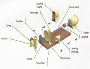
Figure 1: The Components of a Centrifugal Pump
As the pump shaft spins, it turns the impeller inside the casing which adds energy to the process fluid. This allows the impeller to act as a cantilever with a wear ring, seals, and bearings that keep everything in place and fluid from leaking out. The spinning impeller changes the incoming fluid’s direction, which can cause intense radial loads on the pump. The bearings not only reduce rolling friction, but support the pump shaft and absorb these radial loads.
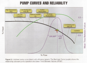
All pumps have a design point where efficiency is maximized, known as the best efficiency point (BEP). This is where the pump runs the smoothest and radial forces are minimized. The farther away from the BEP, the higher the radial loads on the pump (Figure 2).
EXCESSIVE VIBRATION
The pump generally will have a critical speed around 25% the BEP where its natural frequency os reached and excessive vibration may occur, The pump could shake itself apart, first going through the wear ring, then the seals and finally the bearings. This is easy to spot; the pump will vibrate and may begin leaking fluid well before the next scheduled maintenance period.
The BEP should be a factor in the selection of centrifugal pumps. Pums curves demonstrate the strong relationship between pump life, pump reliability and where the pump operates on its curve.
The performance of individual pumps is a combination of design and operating conditions.
The pump’s performance data is provided in the form of pump curves, whose primary function is to communicate or define the relationship between the flow rate and total head for a pump.
Pump curves are provided by the manufacturer and show the operating characteristics of a specific pump type, size, and speed based on the results from standardized tests and test conditions. A healthty pump always maintains the defined relationship between the head and flow.
The pump curve is required for proper pump selection, monitoring pump health and troubleshooting the entire piping system. It will ensure the pump is matched to the system requirements, indicate if the pump is not operating on the published curve, and pinpoint any problems and how to resolve them.
A pump curve is critical for every point. The BEP on the pump curve indicates the peak or maximum efficiency. To operate on the BEP, the system must either control the pressure at the outlet of the pump or the flow through the system to keep the pump operating point (indicated by the red arrow in figure 2).
For example, if the system causes the discharge pressure to rise, the operating point will move to the left up the curve and flow will reduce. If the system causes pressure to drop at the pump’s discharge, the operating point will move down and to the right. Moving to the left or right of the BEP increase forces on the impeller. These forces causes stresses which have a negative effect on the life and reliability of the pump.
If we overlay the expected life of the pump as a function where the pump is operating, we get a “Barringer Curve” which shows the Mean Time Between Failure (MTBF) as a function of BEP flow rate. This curve was created by Barringer & Associates in a study of seal failures in centrifugal pumps.
Using the curve on page 2, the closer the pump is operated to its BEP. The greater the MTBF. As the operating flow rate of the pump moves further to the left or right of the BEP, failures occur more frequently.