Skip to content
Precision flow testing can play an important role in optimizing gas turbine performance. It can determine the performance and expected lifespan of individual components vital to maintaining a reliable and profitable gas turbine.
By combining this information with performance and emissions data, it is possible to suggest improvements to individual components that will benefit overall turbine operation.
Due to the complex nature of individual components and the need for strict tolerances, a small anomaly can develop into a more serious issue that can affect the service life of combustion and hot-gas-path parts. This can result in increased repairs to components, de-rating of the machine, or even taking the gas turbine offline.
Data for each component’s flow test is collected, recorded and reviewed. It is then used to assess the component’s condition and useful life.
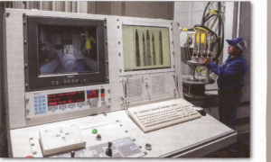
Figure 1: Inspection of 501 FD2 dual fuel support housing in Sulzer’s 450 kV, 5-axis digital imaging X-ray booth
Optimizing combustion flows
Vacuum flow testing replicates the direction of flow that occurs on combustion components while in operation. It helps to verify and adjust the flow rate through combustion liners to ensure temperature uniformity (Figure 1).
Fuel enters and mixes with air in the primary mixing zone of the combustion liner. Supplied air is directed through mixing, dilution and the louver features of the liners. The position, size and effective flow area of these features affect the fuel to-air ratio, flame temperature, flame profile, and ultimately the performance and emissions of the turbine.
The effective flow area of combustion liners may change following a repair. This may result from the removal of thermal barrier coatings and base material, for example.
Therefore, the effective flow area needs to be carefully tested after new barrier coatings are reapplied.
Flow testing of first-stage nozzle vane segments should also be considered (Figure 2).
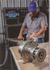
Figure 2: Flow test of 501 DF42 fuel nozzles with steam injection on high-flow test bench 20
The first-stage nozzle consumes a significant portion of air supplied to the compressor discharge case. Turbines that underperform can be affected by the oversupply of cooling air to the first-stage nozzle vane segments. This simultaneously reduces the required air flow for combustion within the liners, limiting the output performance of a turbine. Gas turbines operate in environments where small particles can be ingested and deposited on components. The fouling or blockage of fuel nozzles, for example, can significantly affect turbine performance.
It can also lead to physical damage of the machine. Therefore, blades and buckets should be tested to check that cooling passages are not blocked (Figure 3).
Evaluating uniformity in sets of component flow data can help pinpoint parts that have issues. By comparing data from tests performed when parts are received to those performed after refurbishment, it is possible to identify problems.
Trending this information over time can help develop more informed maintenance schedules and estimates of useful component life.
Liquid flow testing monitors the flow rate of liquid-fuel and water-injection circuits of the fuel nozzles. Liquid flow testing also allows for the visual monitoring of spray patterns, which can indicate component wear or internal blockages. Liquid circuits need to maintain their spray patterns in order to achieve the correct flame profile and temperature distribution. Wear or internal debris may cause combustor burnout. If this occurs, the flame can impinge upon the combustion liner or basket wall and cause component damage.
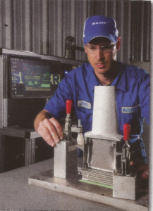
Figure 3: Flow test of 7001 1st stage bucket on high-flow test bench
Assessing liquid flows
Fuel nozzle flow rates need to match those required by the manufacturer’s design specifications in order to achieve the expected output. These criteria may vary from one turbine to another, even if the turbines are of the same model type. An evaluation of flow data should be performed and made available for inventory spares or sets of fuel nozzles. Large operators minimize downtime during outages by using inventory spares.
Spare fuel nozzles, for example, should be clearly identified with a reference that identifies the turbine they originated from and specific flow data. Large organizations that operate multiple turbines in different locations with an inventory pool of spare parts, may have performance issues after swapping out for an inventory set.
For example, fuel nozzles designed for a turbine at sea level will have different specifications than the same model at another elevation. Without a comparison of flow rates, unknowingly swapping these fuel nozzles can reduce performance and may even affect start-up.
It is wise, then, to carefully review flow data from parts being removed from the turbine as well as those scheduled for installation to ensure there are no major differences.
Even when minimal differences are present, this analysis can determine the need for other actions, including changes to fuel valve settings, operational control adjustments or scheduling the turbine for tuning. Ultimately, flow testing aims to remove anomalies from a system, minimizing variation and delivering a more efficient machine. Minimizing temperature spread and vibration reduces wear to components, lowering repair and maintenance costs.